DC5000 Compressor Review
In the Lab for Testing today is the DC5000 Compressor made by AIM Chassis Tech.
Big thanks to Joe Morrow at Chassis Tech!

First impression when this compressor arrived was the size and weight!
The box had staples holding it together and had substantial weight to it.
Here are the install specs of the compressor.
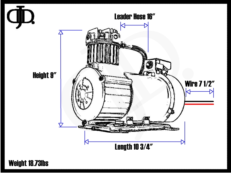
The compressor comes in as the largest Oiless compressors I have tested.
In this review I will walk you through step by step as I take this compressor apart bolt by bolt, and through all of the testing results.
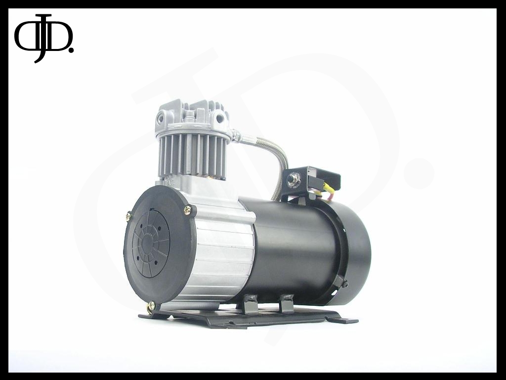
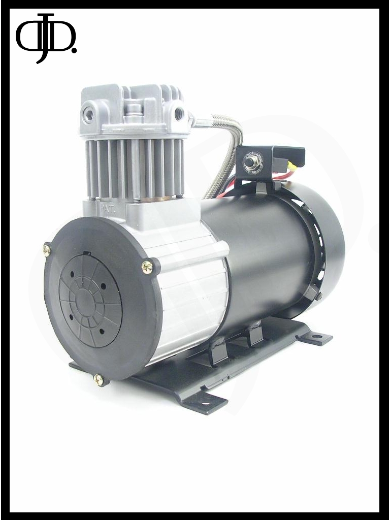
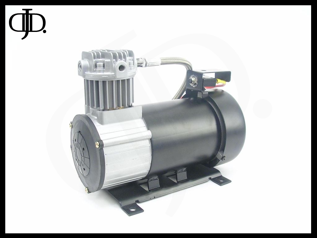
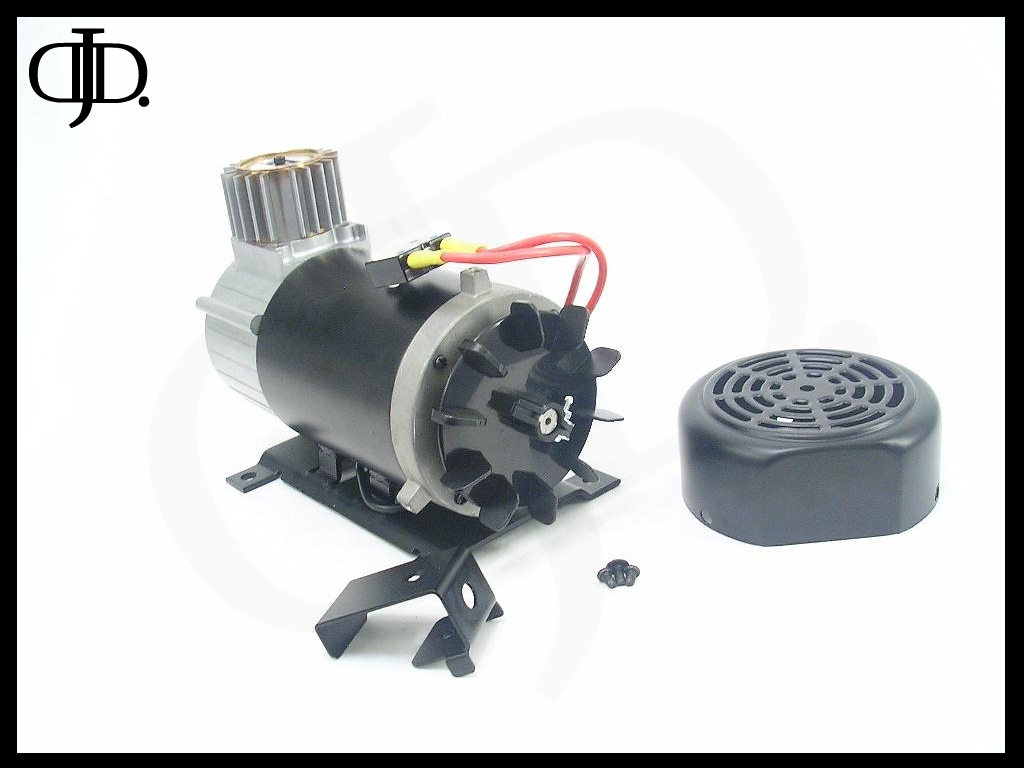
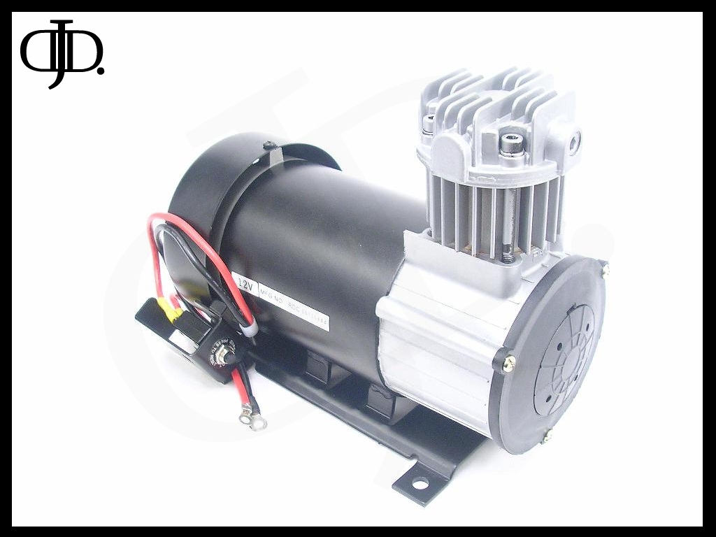
First thing you will notice is the exterior of the compressor.
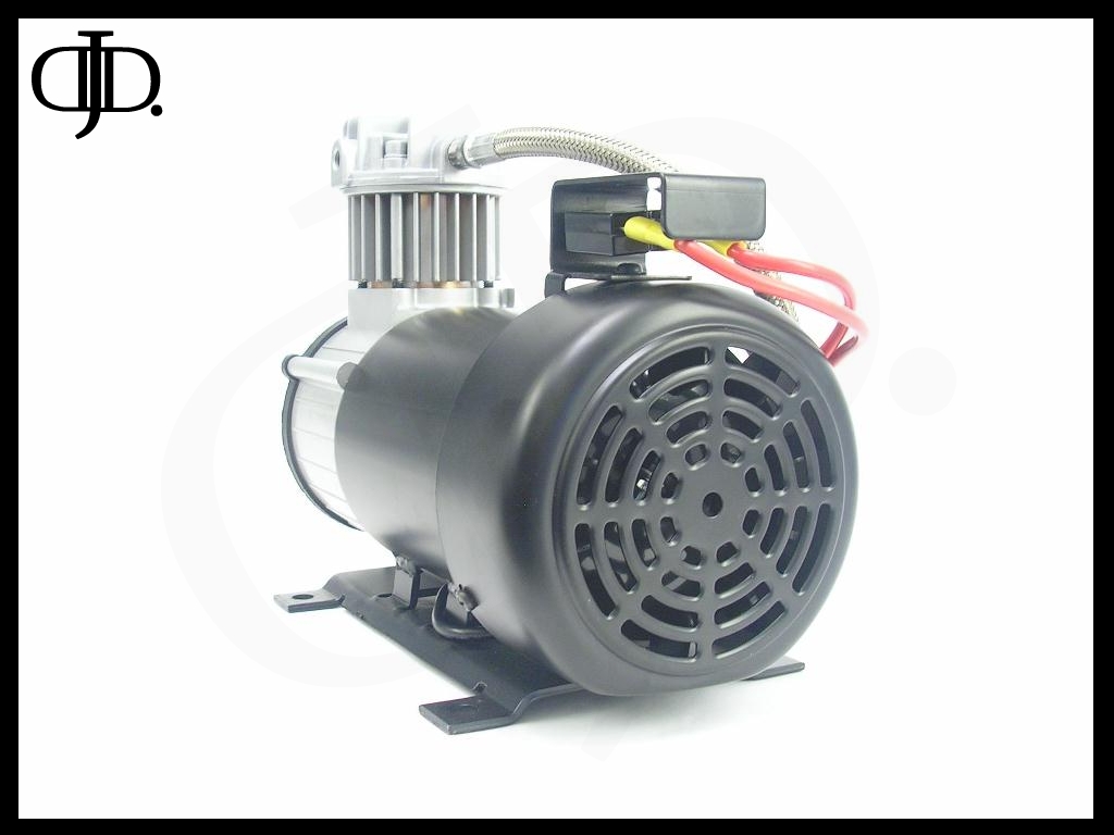
The back of this compressor has something very few oiless compressors have, a FAN! This is a feature I really liked. For during testing the motor stayed quite cool. At the end of this review you can take a look at the thermal imaging results of my tests.
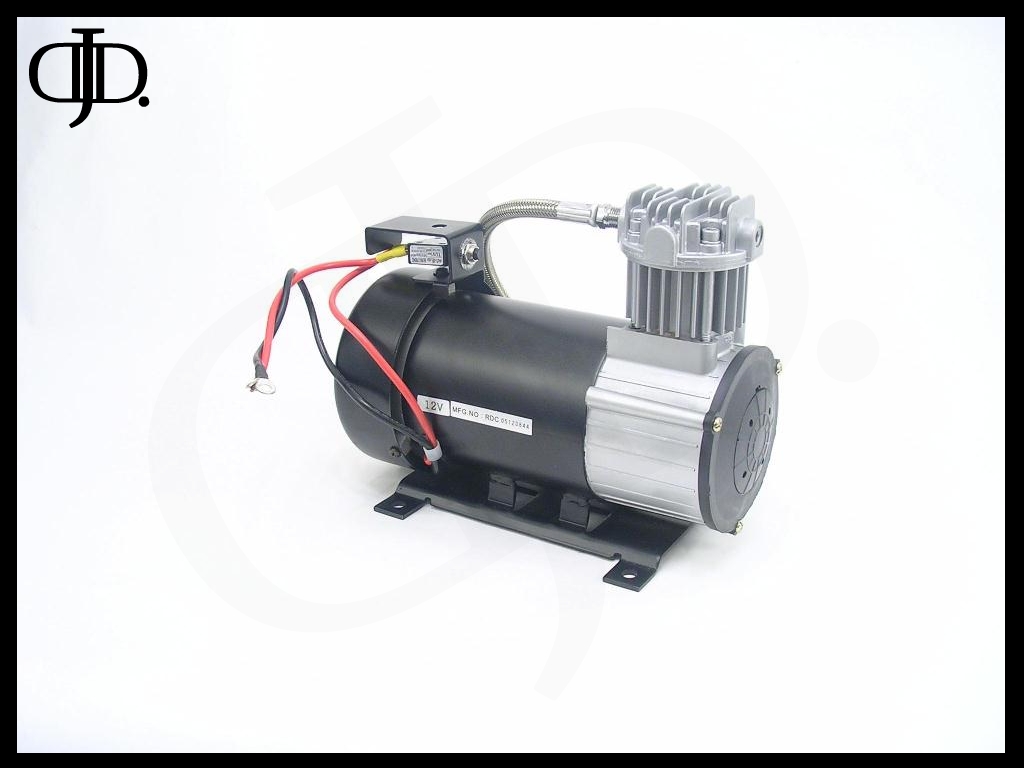
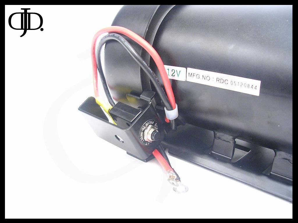
Above you will first notice something interesting going on with the wiring. You will also notice a small black box on top of the motor. What is this you may ask?
Well let me explain.
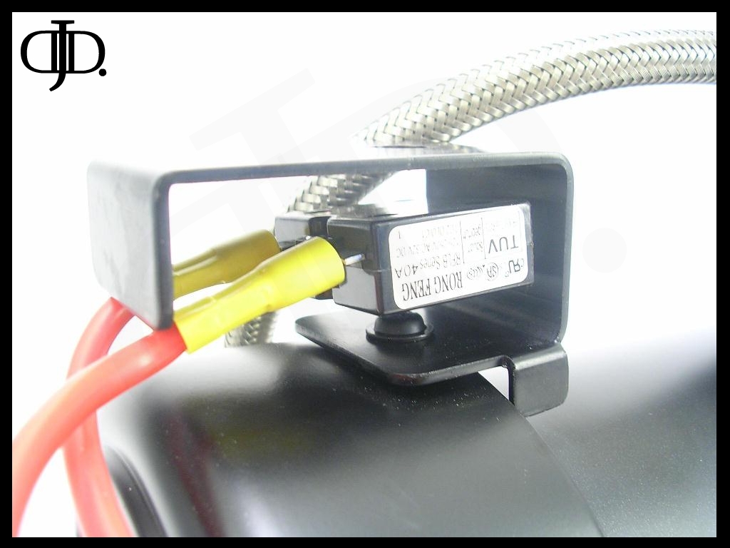
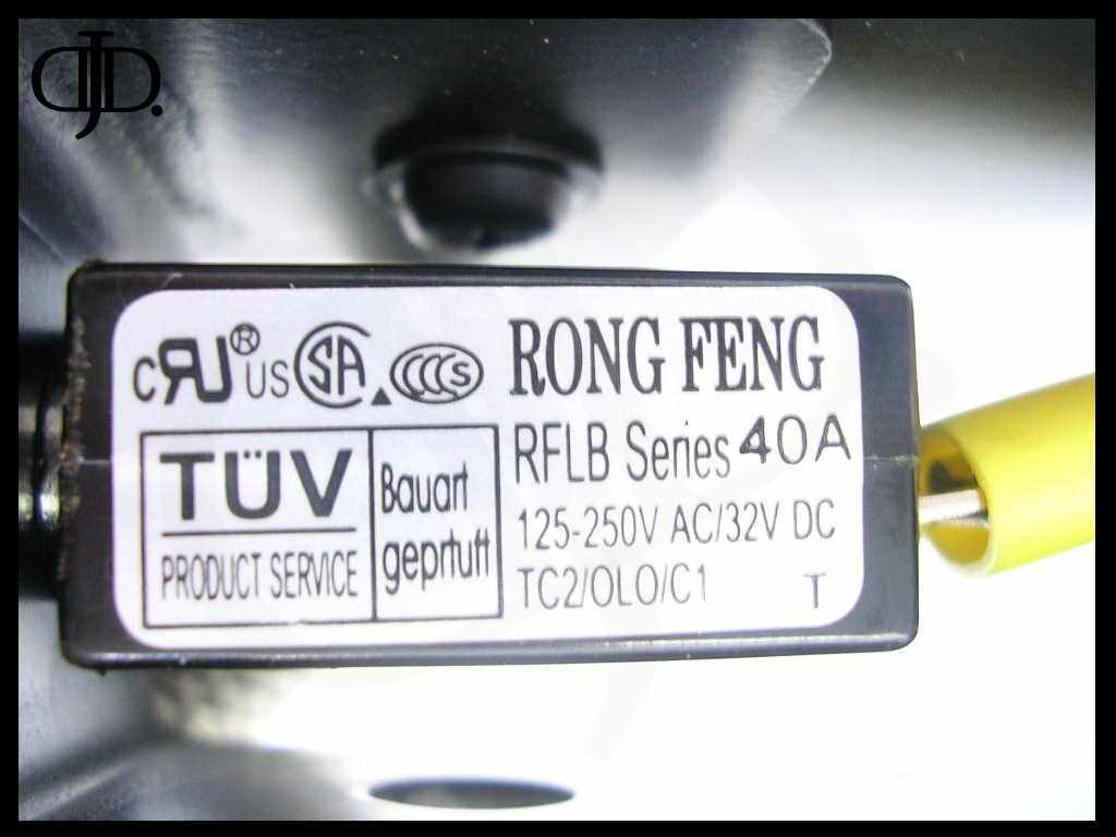
This is a pre installed 40amp 32V Manual reset Circuit breaker.
This is a great feature that I will explain in more detail in the testing aspect of this review later on.
The Main power wire from the relay will go to the breaker then from there on into the motor.
NOTE: This does not mean you do not need to run a fuse! This is merely a secondary precaution to protect the compressor, not your electrical system!
The compressor came with some parts to get you started
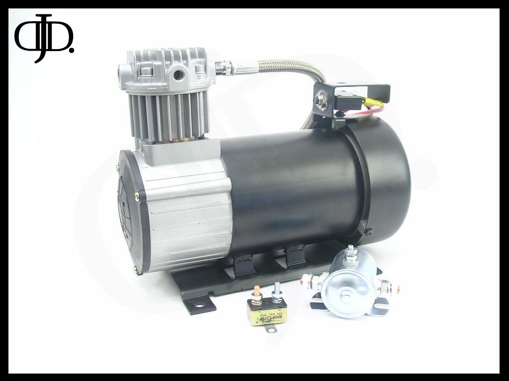
On the left is a small Automatic reset Circuit breaker. On the right is a large Solenoid style Relay.
I ran into a few problems at first though with the install.

The wire that comes from the compressor is two small to fit directly onto the relay included with the compressor. So my next thought was the secondary circuit breaker needed installed. The wire fit right onto the breaker, the problem was the compressor wire was not long enough to mount the breaker flat on the ground without pulling the connector from the compressor mounted breaker. From here you will need to supply your own wire from the remote breaker to the included relay and you are ready to go!
Next I found in the box an included Leader hose and fittings.
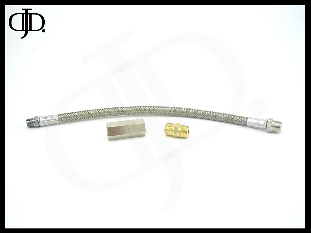
The leader hose has two fittings crimped onto it. On the Left is a ¼” NPT male fitting that fits into the head of the compressor. On the right is a 3/8” NPT male fitting that fits into the included check valve (front left) and then (front right) is the included 3/8” male/male nipple to connect everything into your system.
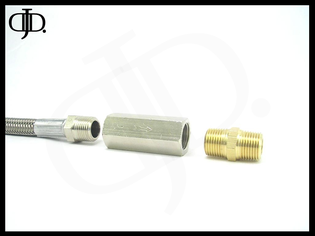
NOTE: make sure the arrow points AWAY from the compressor / leader hose
Everything fit together well.
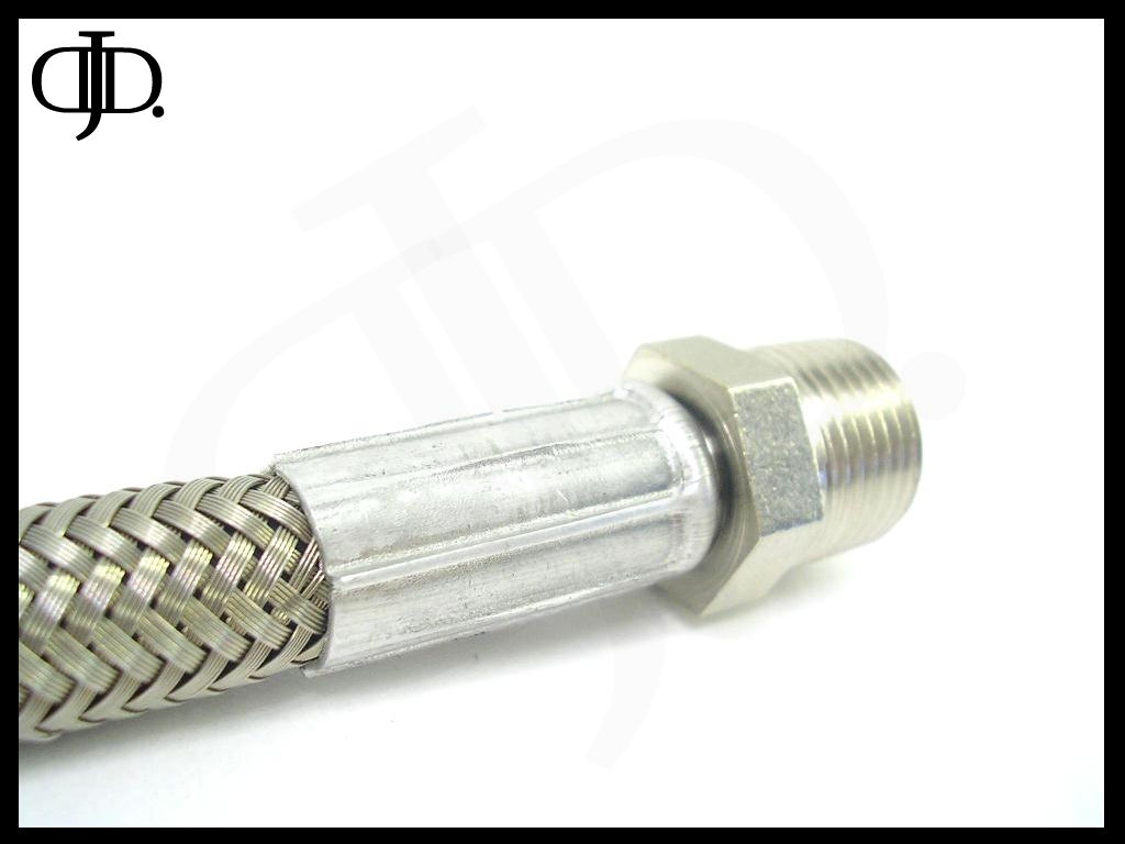
One thing I want to point out here the leader hose does not have a swivel fitting. This means there is only two ways to attach the compressor to your system,
(1) Leave the compressor un mounted and thread the hose into the compressor first then rotate the compressor in your hands while you thread the hose into the tank.
(2) Mount the compressor now remove the head from the compressor and spin the head in your hand as you tighten the leader hose into the tank.
Either way you do it make sure you use your thread sealant of choice and do not over tighten. On the compressor I tested the Leader hose only threaded into the head with two threads. But it sealed no problem.
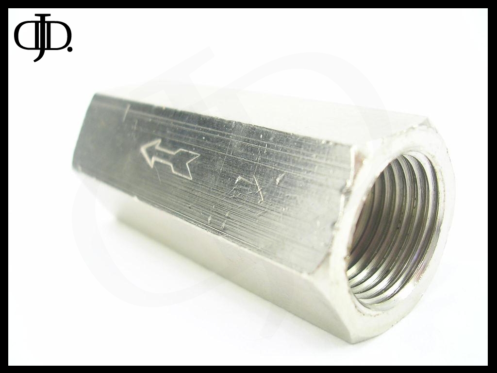
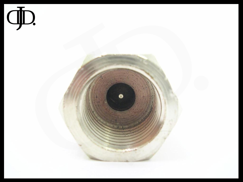
The check valve right out of the box had nicks dings and scratches all over it (even inside). This may have been from bouncing around inside the bag of parts. But it did not look pretty when I installed it.
With that aside the Check valve is large and held back 200PSI no problem. And held tight through all of my testing.

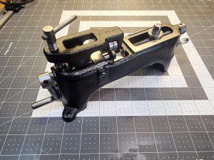
Here is the Circuit breaker, this unit is well done and has a great finish on it. As well as large lug terminals for terminating your wires.
The crimp seal on the head of the unit is well done and was sealed tight from the elements. When submerged under water no air bubbles where present.
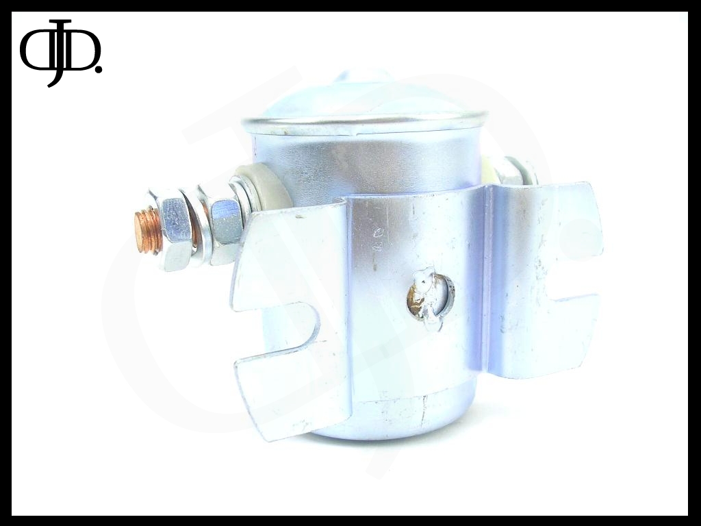
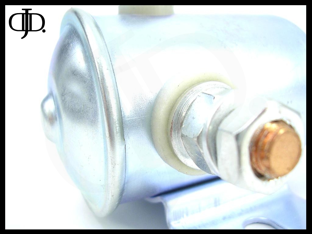
The solenoid only has one post on top for the control wire from your pressure switch.
What does this mean? Well this means that you can only use a Positively switched source for your pressure switch. And the solenoid has to be well grounded through the mounting feet pictured above. So keep this in mine when you install the relay.
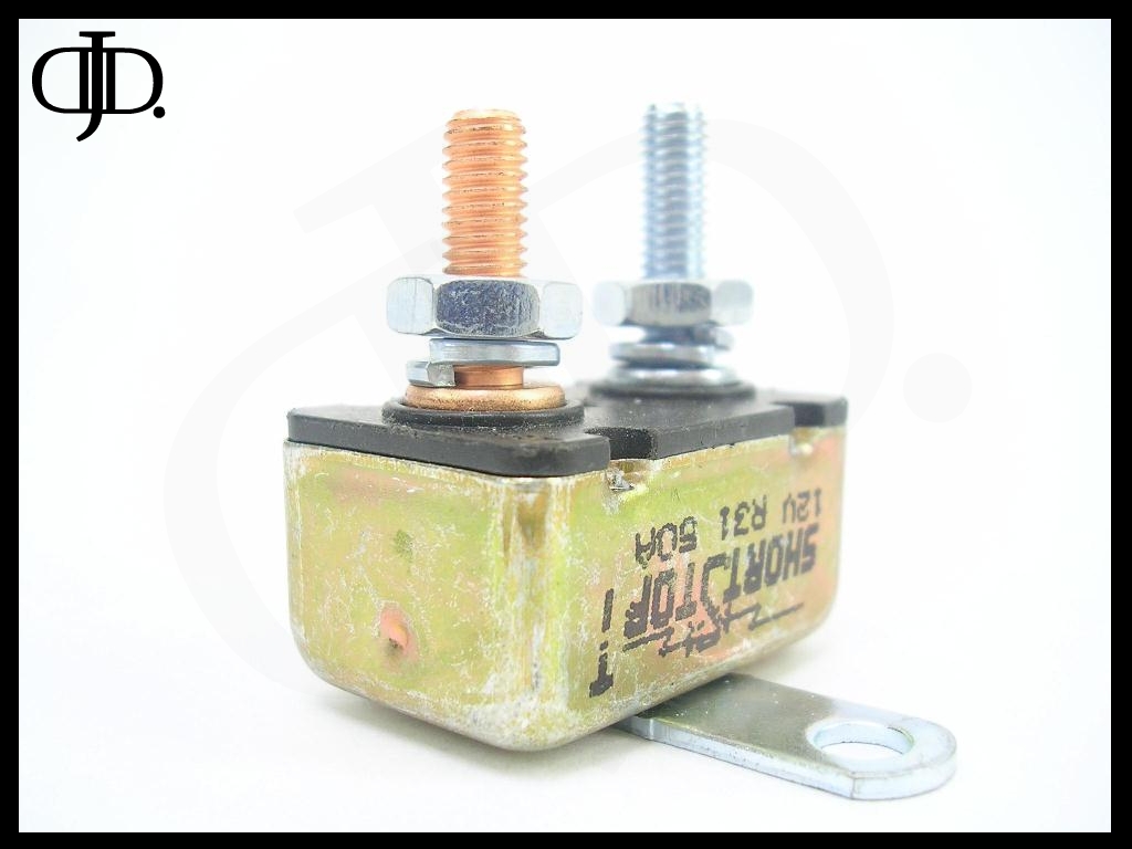
Last here is the ‘Short Stop’ External Auto reset circuit breaker. This unit is ratted at 50Amps at 12V and will trip out if the current load exceeds 50amps for more then 6.3Sec. I installed the (copper) lug to the battery or relay side and the (silver) lug to the compressor.
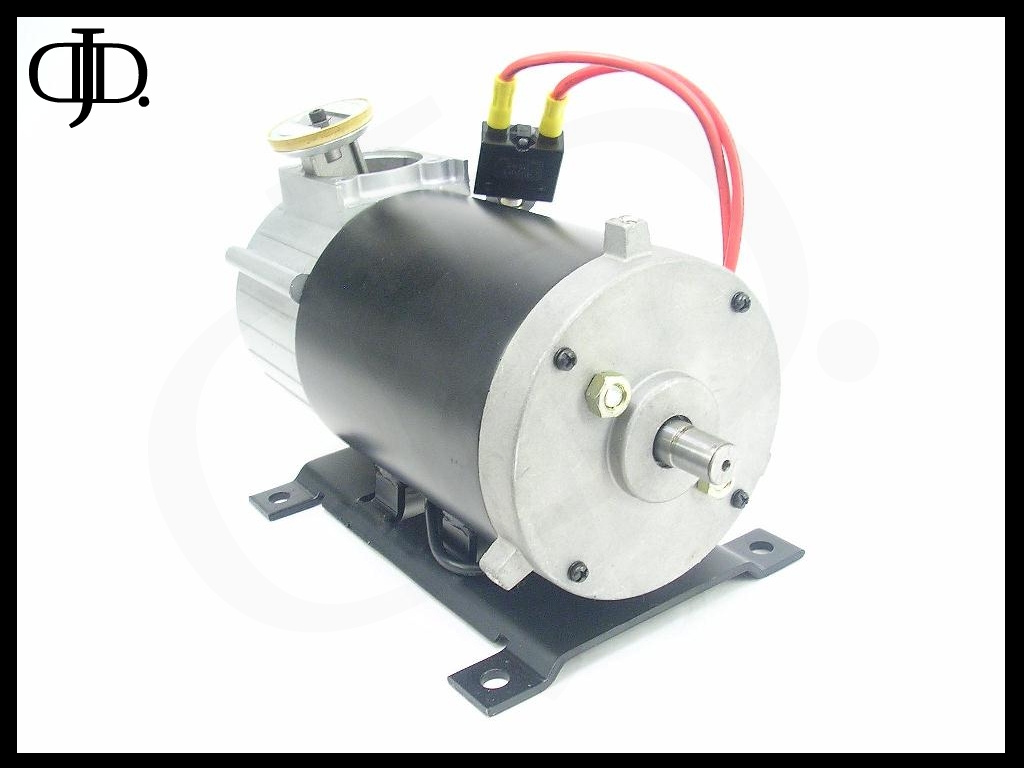
Now that we have gone though all of the Accessories that came with the compressor. Let me go over the finer details of the compressor itself.

The mounting platform is all Steel and has (4) small tabs that are welded to the motor body.
The feet do not come with rubber isolation bushings. But the base is very solid and was easy to mount.
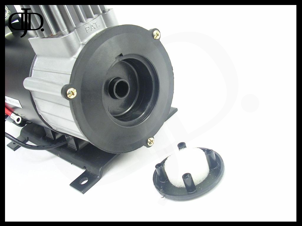
On the front of the compressor is a plastic front cover over the crank case. In the center of this is a small 2.5” diameter plastic circle with a small indent for a standard screw driver. Insert the screw driver and gently pry out and away and the filter door will pop free from the case.
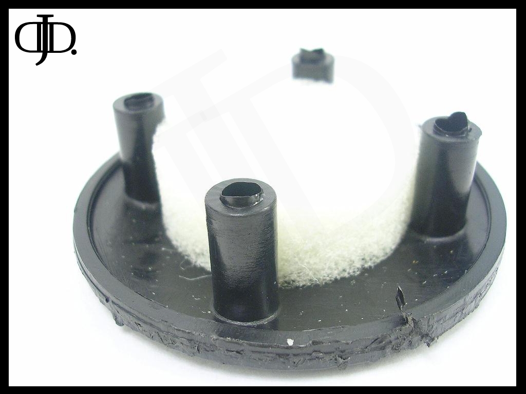
The filter is a hard foam like substance ( has the feel of Styrofoam) and is held in place by friction from the four plastic posts. It is very easy to pop off remove and clean.
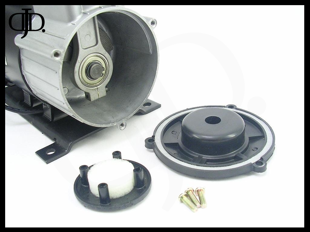
When you remove the (3) Gold screws on the crank case cover everything will pop apart for easy service and cleaning.

The seal between the Cover and the crankcase was a white thin gasket.
The cover also has small reinforcement ribs on the back side.
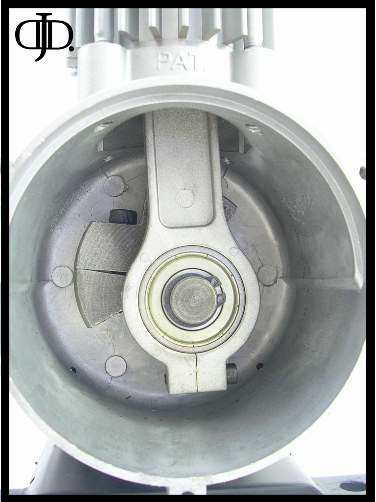
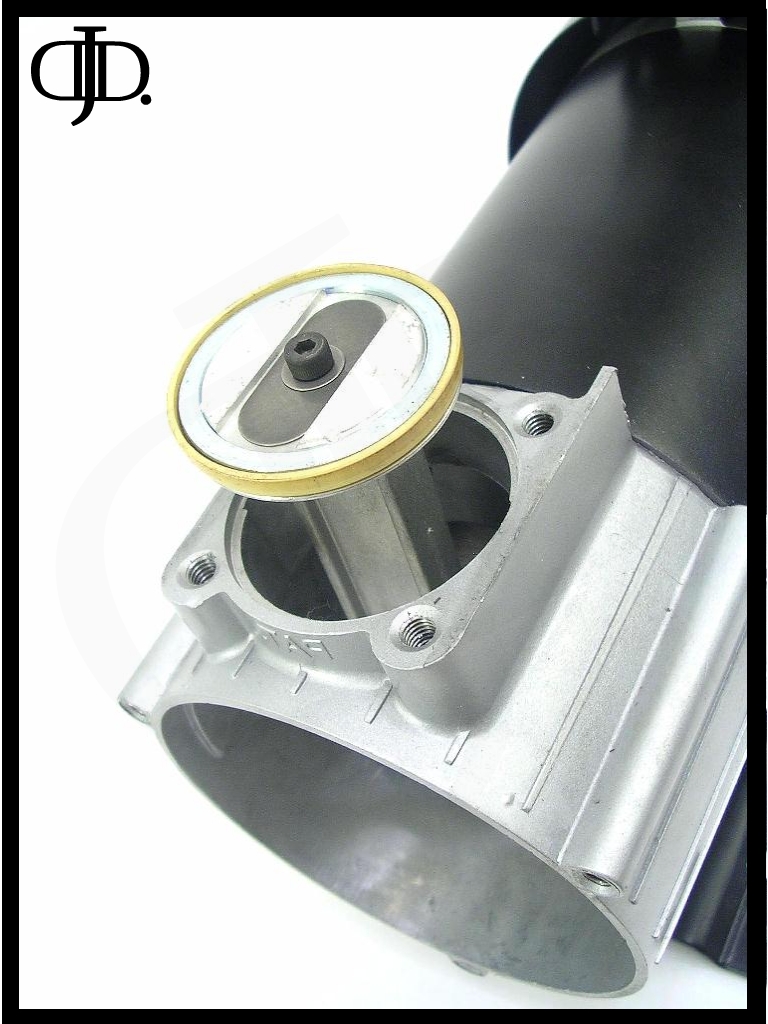
Here is a shot of the inside of the crank case.
Everything in here just like the rest of the compressor is over sized. The counterweight piston and bearing are all large and beefy.
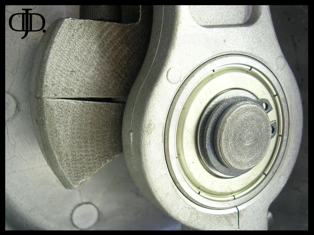
The counterweight is not broken, it simply has a slot machined out of it that is used to tighten the counterweight/ crank shaft to the motor.

The bearing in use is a nice high speed bearing out of Taiwan. (With an all metal seal gasket.) I also noticed a small spacer on the piston crimp joint; my guess is this is used to adjust for slight casting deviations.
Last when used with a strobe a scope. The bearing and snap ring did not move they remained in there locations throughout the pistons travel as well as under load.
This means that everything is snug and within tolerance.
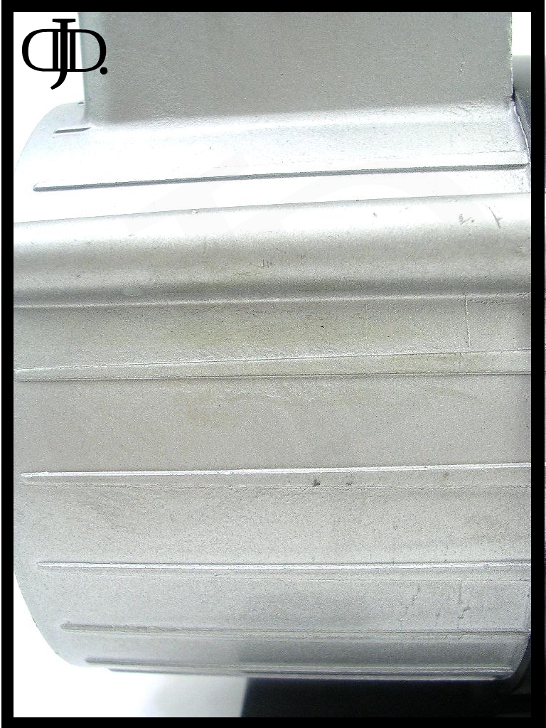
Here is the outside wall of the crankcase. The casting although rough was solid and with no cracks in the body or mounts.
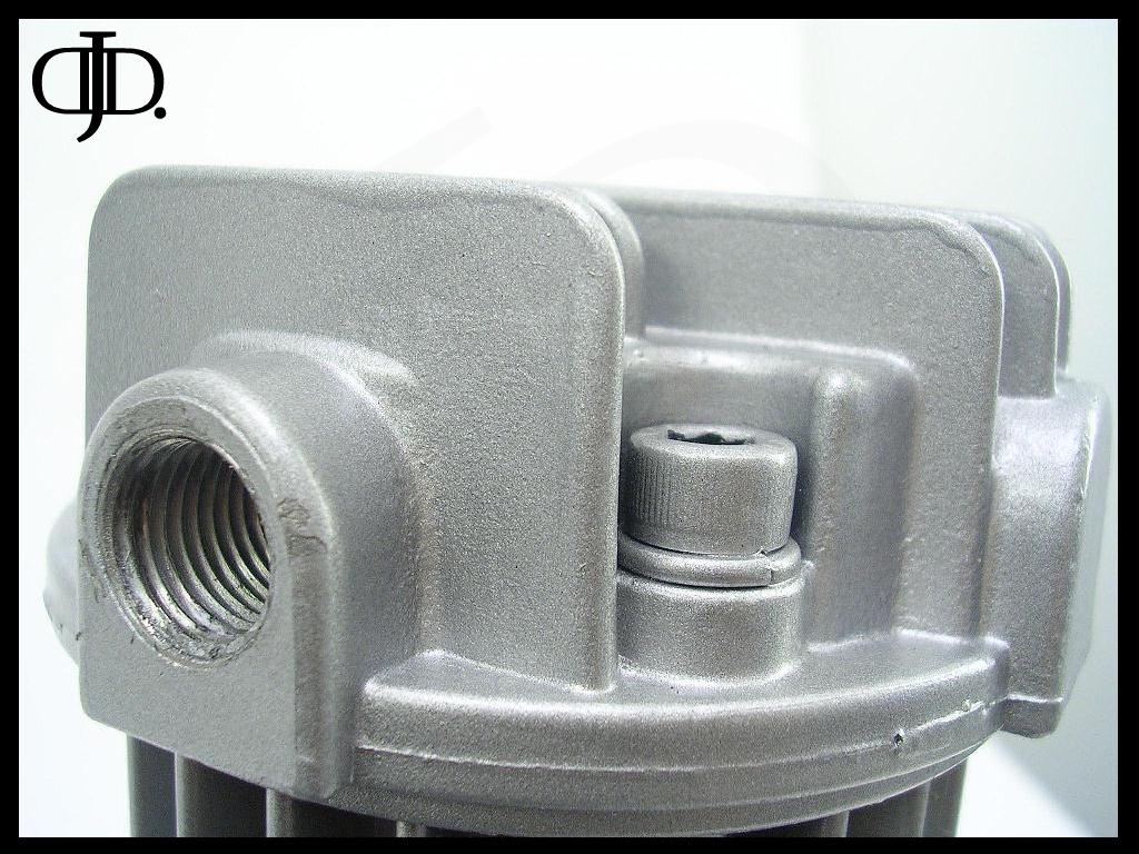
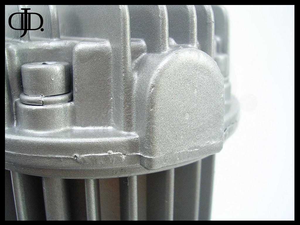
The head of the compressor was a very rough casting that also had a few paint runs and clumps. With close inspection the head and bolts where painted after assembly.
A small remnant to the above is the overspray that was found on the motor body from the head.
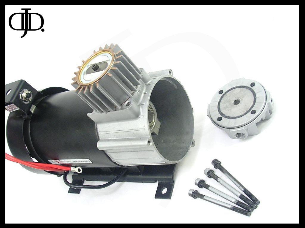
Removing the head exposes the massive piston and solid head.
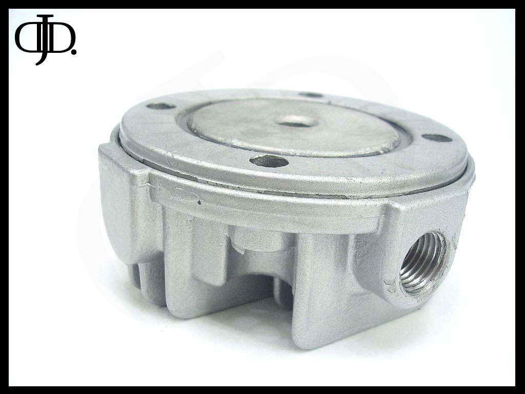
The head is made up of 2 parts the finned head and the valve plate.
The seal for the head again is a small gasket (black ring) in the above pic.
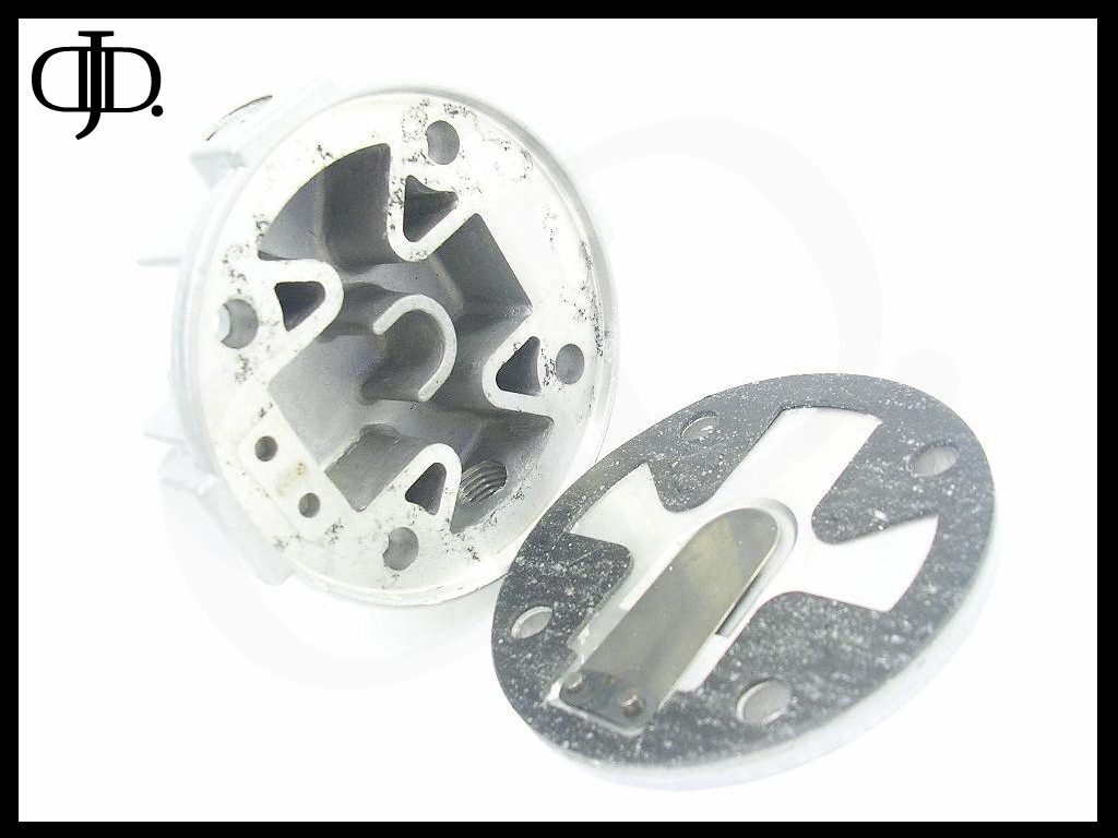
Here is a shot of the head opened up. You will find the large over sized output valve and the underside of the head.

The valve plate is thick aluminum and has the same gasket material to seal itself to the finned head.
The valve itself is actually held in by the finned upper section. The small black metal retainer is just to hold the valve in place when working on the compressor.

The head is very open. First thing you will notice is the ‘U’ shaped metal in the center this is the output valve strain relief, this will prevent the valve from over extending during operation.
A nice feature is the head is tapped for (2) outputs. The far one is the stock output. The Close one with the Allen plug can be used for a second output.
Also far side left is a 1/8” NPT female port that is ready to go just needed drilled, if you wanted to mount a gauge this would be a great feature.
After the head has been removed you can see a very unique valve design, the piston has two valve holes to allow more air through. The single valve covers both orifices. In the above picture the Piston is at Top dead center.
With the cylinder wall removed here is everything from the frond end assembly.
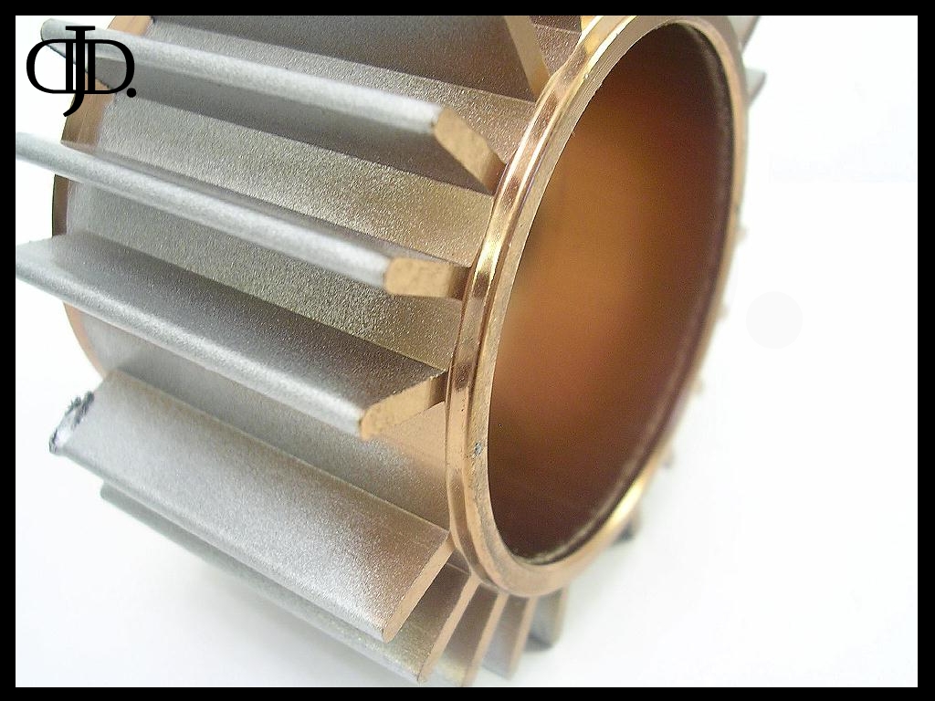
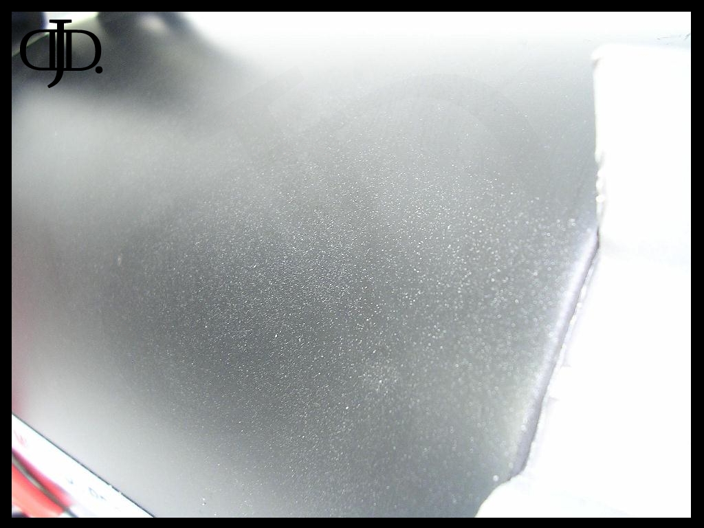
With the cylinder wall removed. You can see the cylinder wall is hard anodized aluminum to prevent wear.
But for some reason this beautiful cylinder wall has been painted over. It does easily flake off. I had to be extremely careful handling this unit as to not scratch or nick the paint.
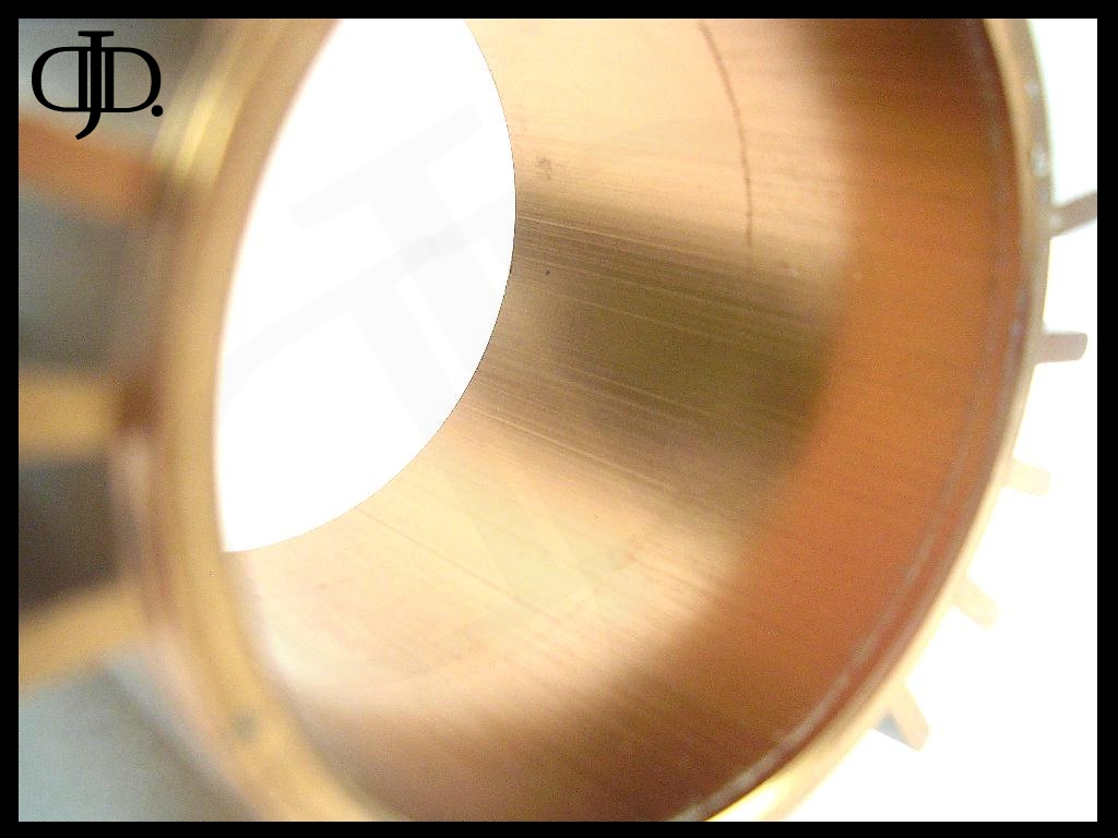
The inside surface of the cylinder wall even after my testing remained extremely smooth with little sign of wear.
The inner groves although slightly raised where in the direction of travel so they did not effect the pistons seal.
NOTE: if you take this compressor apart mark the location of the cylinder wall and the piston, so the machine marks align up with the wear groves on the piston ring.
The Allen bolts used to hold the head together are painted silver after they have been installed. So when you have to service the compressor make sure you re align the bolts so the silver is on the outside.

The piston ring is your standard Polytetrafluoroethylene composite material. And revealed good wear during testing.
The piston ring is held in by a steel retainer ring that has been crimped into place.
One thing I noticed about the valve was it was loose. It was able to be rocked back and forth. The Allen bolt was tight. My thought was this was intentional, as to why it is needed I am unsure.
Here is a shot of the crank case the body is solid. Where the cylinder wall and head mount the metal has been beefed up. In the back inside of the crank case opening you can see part of the reinforcement.
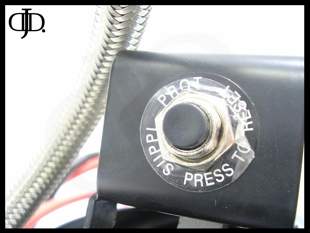
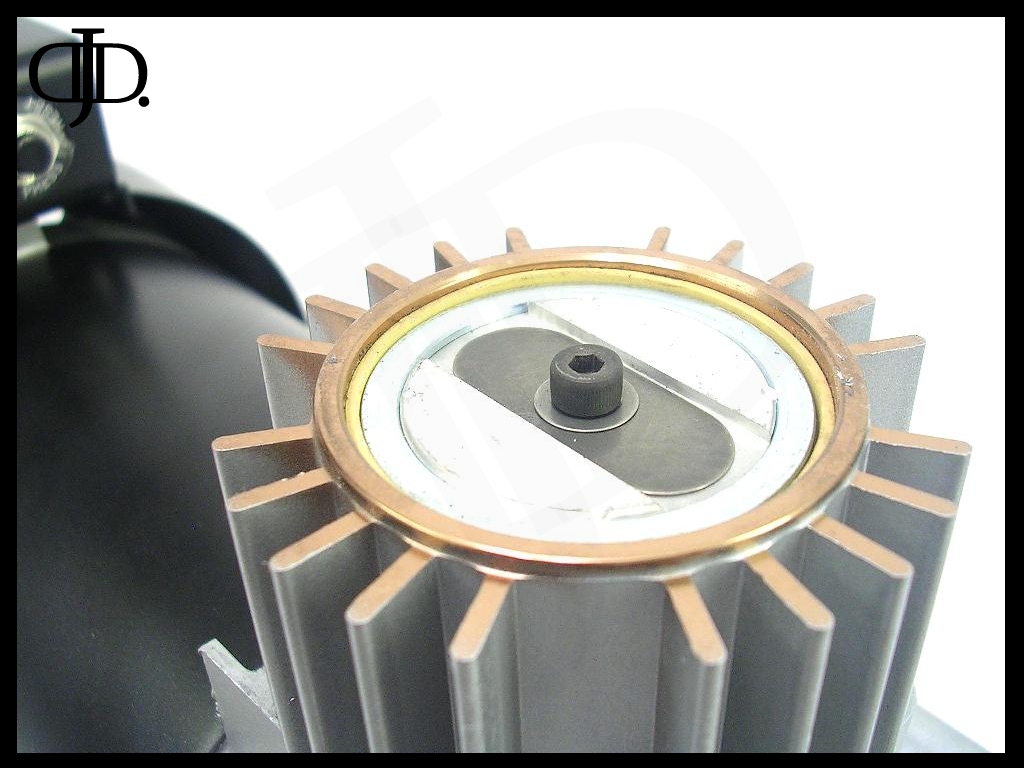
The back fan assembly is easily accessible. To remove the back fan cover there are (3) small Philips screws located top dead center and on each lower corner. To access the one on top you will have to remove the circuit breaker first, this is done by removing the nut on the reset button and sliding it out of the way. This will allow access to the screw for removing the bracket.
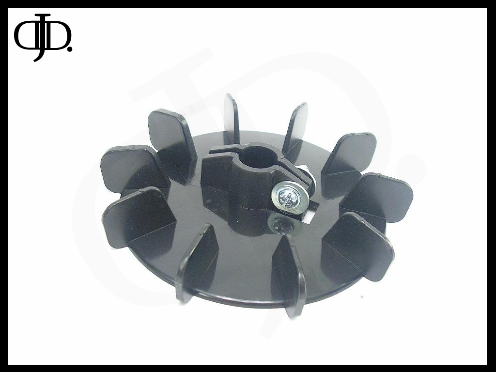
The fan is a solid black plastic unit. With a small jam bolt to hold it to the motor shaft. I had no problems removing this.
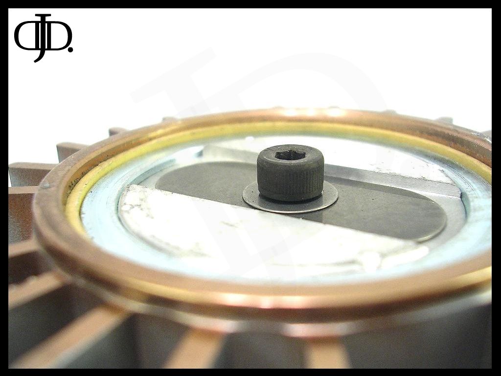
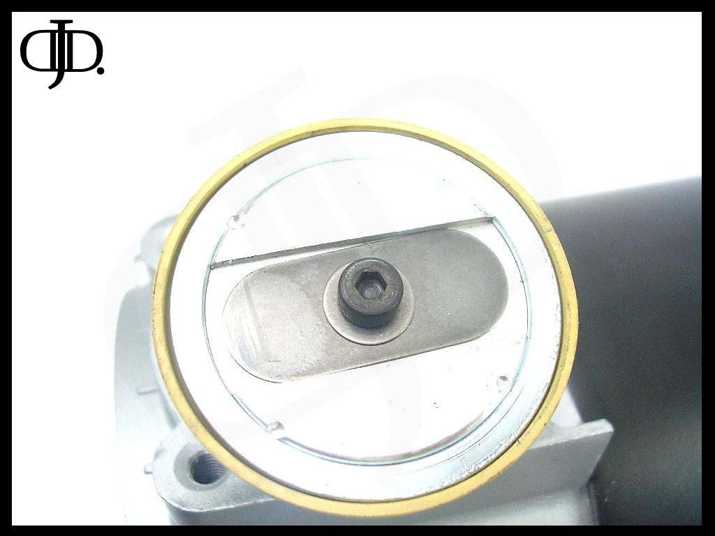
After removing the shroud and the plastic fan you will be left with what is above. A solid metal end cap.
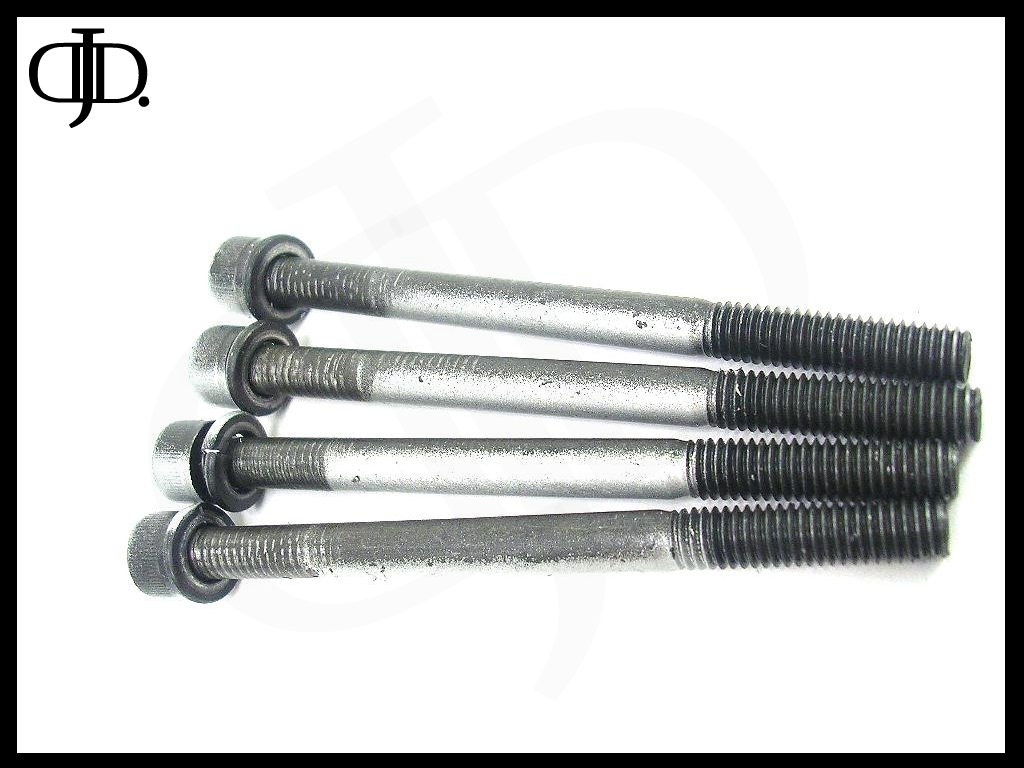
The (4) small black screws hold the rear and cap and front crankcase together. The large gold nuts hold the brush assembly to the rear cover.
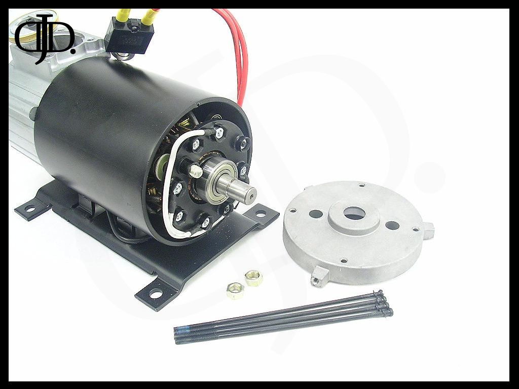
Remove both the (4) black screws and the (2) gold nuts. NOTE: these may be very tight.
I was surprised the end plate was quite thick and (3) of the bolts had lock tight on them.
The brush holder was then easy to remove. I simply had to remove the small plastic wire retainer and slide everything out and away. This makes it real nice for when you have to service the brushes. Or if you have one stick.
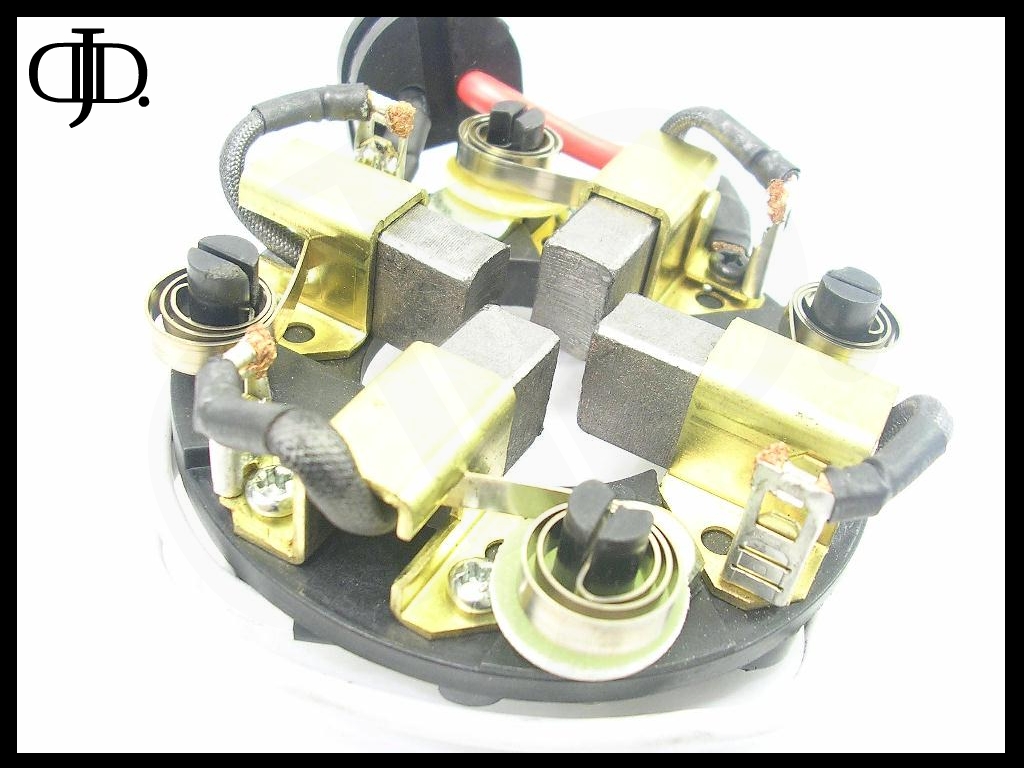
This part I was amazed with. It was nicely done. It is a (4) brush DC motor. You do not see that on almost any of the smaller oiless compressors. This evenly distributes the load across (4) brushes as apposed to (2) normally used in most compressors.
The brush holders and guides where all metal. Even the tension springs where of nice quality.
And if something where to go wrong, you can simply replace just the above part with very little hassle.
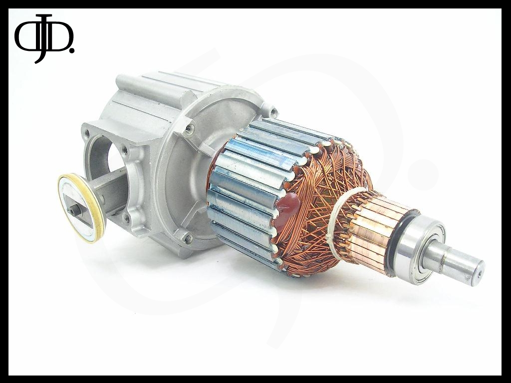
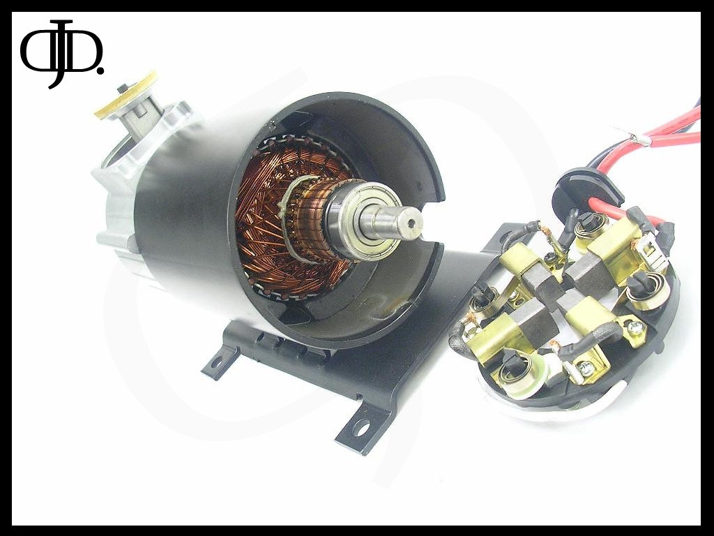
Here is where the compressor really shined to me. The motor armature was very well crafted.
I was very impressed with the construction of the motor itself. Everything from the wrapping of the motor down to the use of high end bearings front to back. Take a look at the (4) mounting points on the inside of the crank case, I will talk about these later.
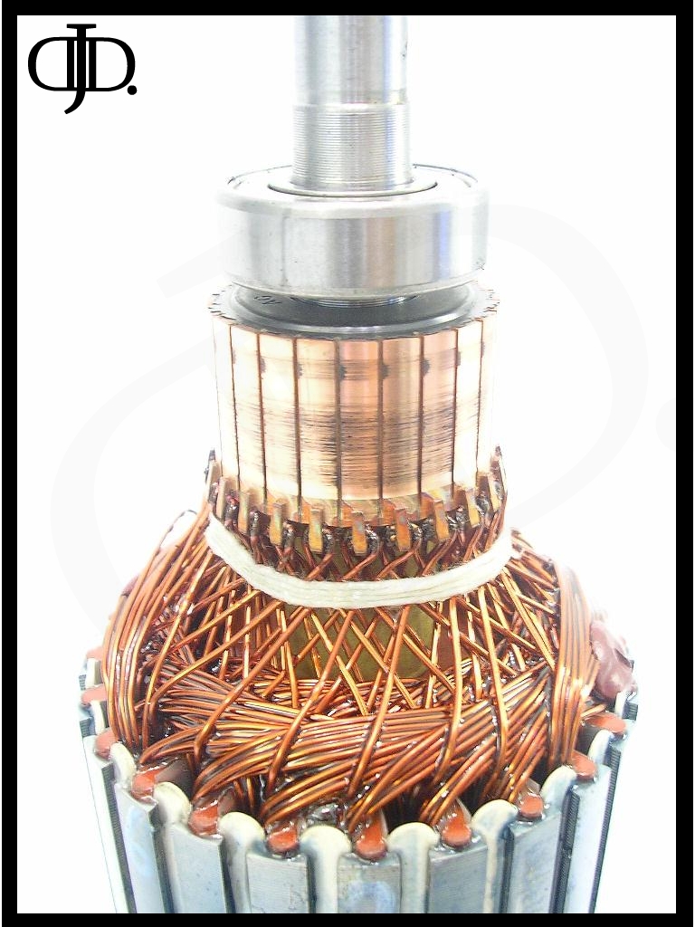
The commutator showed signs of wear even before I tested the compressor. This tells me the motor is at least tested at the factory before it is shipped out. Although there are signs of uneven brush wear, the motor is brand new, and this is normal until the brushes fully break in.
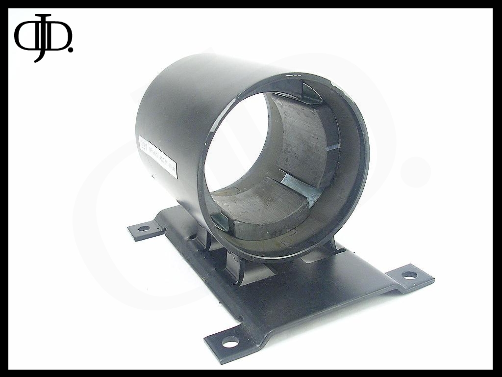
The motor housing is a thick ¼” steel and welded firmly to the base plate I showed earlier.
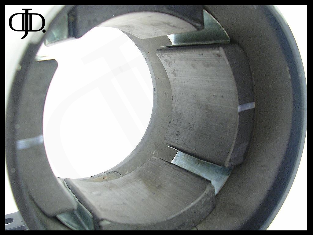
The motor consist of (4) massive ceramic magnets. The (4) gaps are where the mounting bolts pass through.
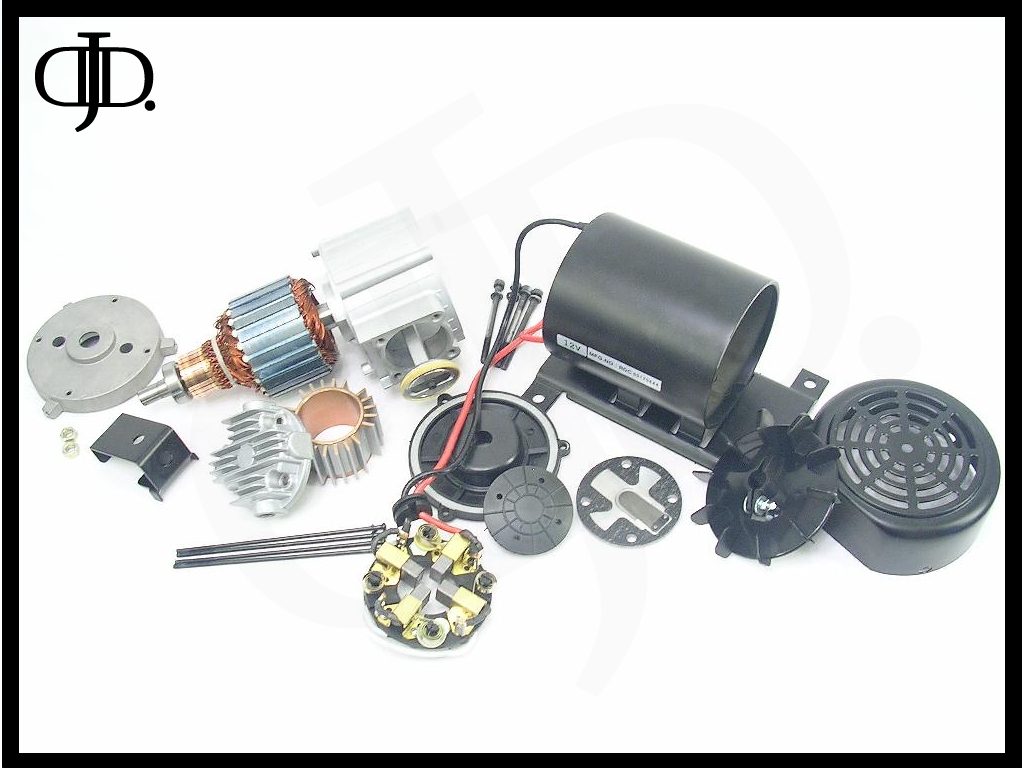
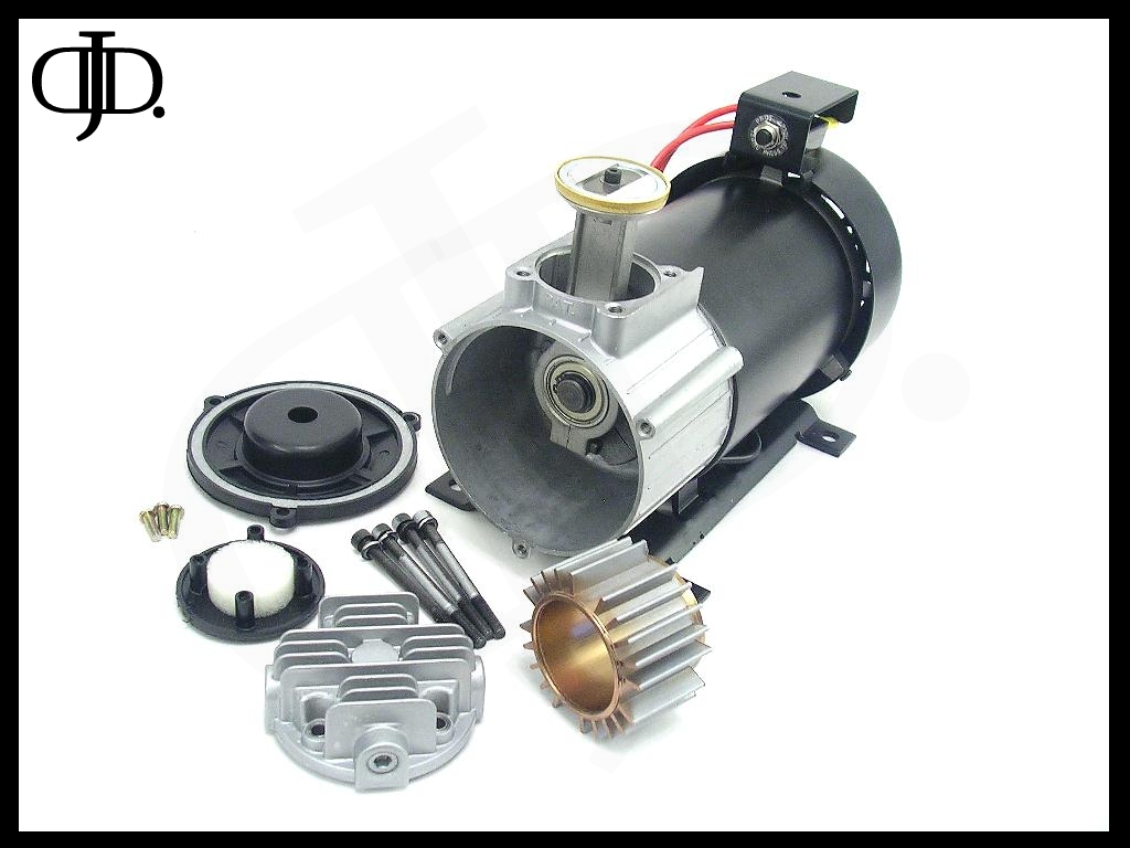
Here is the entire compressor all taken apart. This unit consist of allot of part. By far the motor is the best constructed part of this compressor.
I took it upon myself to relocate the circuit breaker. Simple to do, all you need is to remove (2) screws and swap its location.
NOTE: this will block one of your mounting feet like this. You will need to mount the compressor first then install the breaker.
The wire on this compressor is 10AWG and is very stiff. The red and black power leads are the same length, but the red wire has been cut in half and passes through the circuit breaker. So on top of the compressor the red wire became effectively very short.
The way I have it now gave me 7 and ½” of wire lead length for both the red and black wires.
Now onto testing!

Above is a time laps thermal imaging of the compressor under operation.
The above test was a continuous run at 100PSI for 10Min starting at 66.56F
The final head temperature was 275.5F
The thermal image shows how well the cooling fan kept the motor cool.
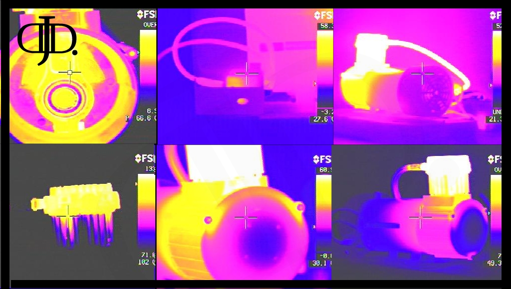
The compressor with its plastic front cover allowed the air filter to remain almost at room temperature as the compressor was running.
Although the wires did heat up. The amp draw of this compressor was well within the rated spec for that size and length of run of the main wires.
One thing to also point out. (Top left) the center of the bearing remained cool during operation.
The only thing that bugged me was the Circuit breaker did run hot during the tests 136.4F
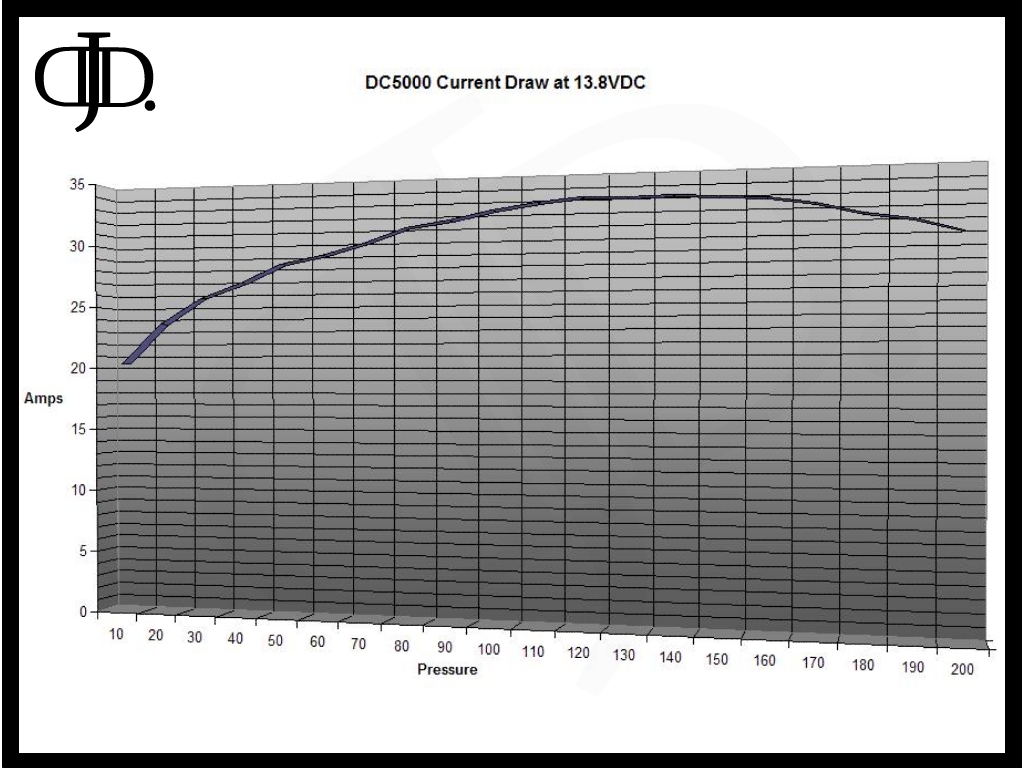
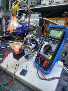
Above is the recorded current draw of the compressor filling a 5 gallon air tank from 0 to 200PSI
Max recorded current draw was 33.9Amps at 130PSI
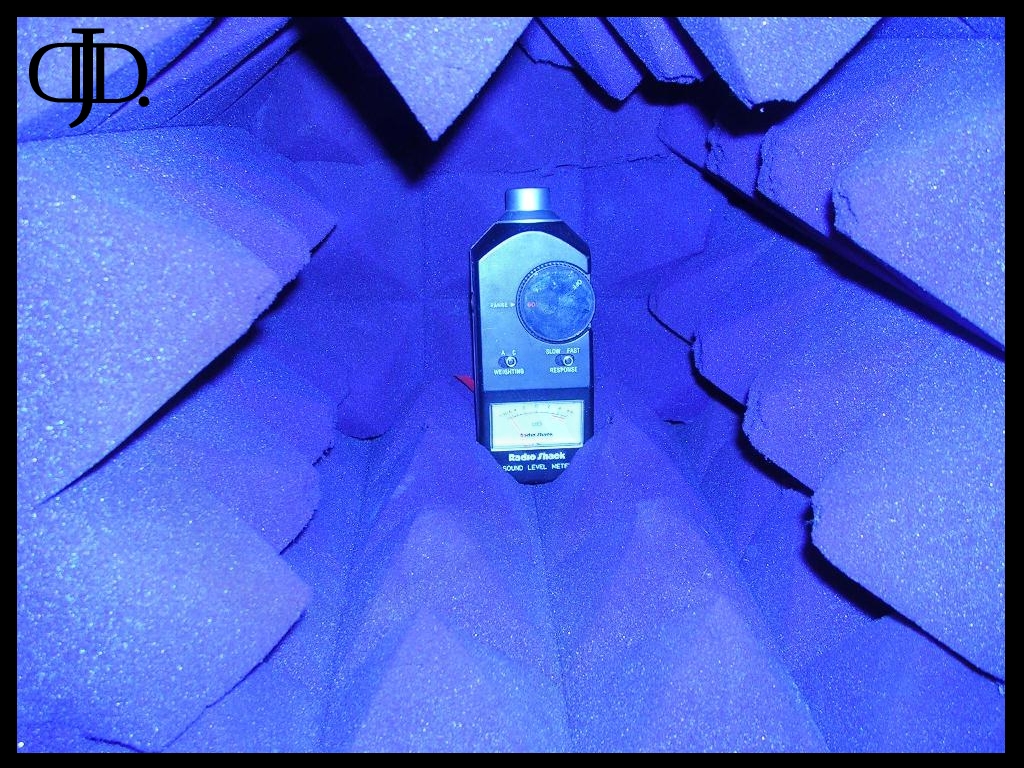
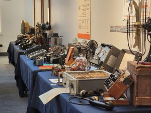
The above is a picture of my anechoic chamber; chambers such as the one above are used to measure the sound pressure levels of an object. The chamber will remove all traces of an echo. Similar to being outside with no walls for miles floating in mid air.
The room has an effective ambient db level of 0db.
The compressor was tested in the above box at 13.8VDC at 100PSI the compressor produced 85db in the A weighting at 1 foot at the loudest point on the compressor.
I would like to mention this compressor does vibrate more then most I have tested. On my pad I was getting a full 1/16” vibration swing at the head of the compressor during operation.
This high of a vibration when mounted to sheet metal can and will cause excessive noise. Hence why most people find this compressor louder then others.
FLOW RATE!
Ok now here is the part you have all been waiting for in this review I am sure.
The flow rate of this compressor at 13.8VDC was 1.4721 at 140PSI
This puts the compressor faster then the Air-Zenith that is 1.24CFM at 140PSI as well as the Viair 480C at 0.92CFM at 140PSI also it puts it damn close to the new Viair 490C at 1.58CFM at 140PSI
There have been so many claims as to this compressors performance in the past from people who have had them. It is nice to finally put this to rest and know that this compressor truly is as fast as those have clamed it has been in the past.
How would I rate this compressor?
This is a real tough decision for me on this compressor. This compressor is fast solid and has a well built motor. But the fit and finish of the compressor leaves allot to be desired. And there was one fatal flaw I just can’t can’t past in my mind.
RESTART!
A compressor needs to restart at any time to be a reliable part of an air suspension system.
This compressor when tested would run from 0~200PSI no problems. But when I went to restart the compressor shortly after it had just shut off I found the motor would lock up. The motor would pull 117amps! Yes full locked rotor is 117amps. It held this 117amps for 6.3 seconds before the onboard circuit breaker tripped.
So the next time I waited a full 10Min before attempting a restart at 110PSI and found the compressor to still be locked.
The check valve was tested and found to be operating perfectly. The problem relied on how well I had everything sealed. The leader hose and head had no leaks so the head pressure remained in the head preventing the motor from running one cycle. It would get locked about ½ way through compression.
So I steadily dropped the head pressure until I was able to attempt a restart. At 87PSI the compressor would reliably restart.
Any pressure above 87PSI the compressor restarting was hit and miss.
I think this is where so many people melted the wires in there truck or burn up there compressor.
You MUST use the included circuit breaker with this compressor. NEVER bypass it. Also please use a fuse on your system. An 117amp load for 7 seconds can cause allot of problems.
The compressor is rebuildable, but instead of ‘O’ rings the compressor relies on gaskets. As we all know gaskets in time bond with there matting material and cause the gasket to rip. So when you rebuild an older compressor make sure you have replacement gaskets on hand.
Even though this compressor is very fast I find that the excessive vibration, low restart pressure, and sheer size, put this compressor in a 6/10 ratting.
As long as you keep the above information in mind when working with this compressor you will have a great experience with it.
Cheers,
~Doug
© 2008 DJD Laboratories
If you have any questions please E-mail DJD@DJDLabs.com
All pictures and information depicted on this page are the sole intellectual property of Doug DeHaven and no information presented on this page can be held against Doug DeHaven in the court of law.